EEGLAB electrode coordinate systems
EEGLAB supports electrode coordinate systems with the nose pointing towards the direction +X (the origin - loosely defined - is situated at the center of the head, and the top of the head points towards the direction +Z). Electrode coordinate formats where the nose points in another direction are automatically converted, so the nose points toward +X. In terms of distance units or fiducial definition or position, EEGLAB is quite flexible. Nevertheless, for BIDS compatibility, the EEGLAB coordinate system for scanned electrodes is equivalent to the CTF MEG coordinate system, with the center of the head being situated between the left pre-auricular (LPA) and right pre-auricular (RPA) fiducials (see below).
Three fiducial or anatomical landmark points (i.e., nasion, LPA, and RPA) are typically used to define a system. See this FieldTrip FAQ page for details on how the origin and the axes are defined in different systems.
We recommend importing the BEM template electrode file (default) to assign electrode locations based on 10-5 channel labels, if digitized electrode locations are not recorded. If digitized electrode locations are imported into EEGLAB, make sure that the orientation of the coordinate system is correct, with ‘LPA’ on the left (+Y), ‘RPA’ on the right (-Y), and the nasion facing forward (+X; up). If necessary, electrodes may be rotated in the horizontal plane using the Rotate Axis push button of the EEGLAB channel editor (menu item Edit → Channel locations).You may use scanned electrode coordinates and EEGLAB’s get_chanlocs for electrode digitization and MRI images for custom head models and localizing EEG sources.
EEGLAB template files
EEGLAB uses the BESA electrode montage for 2-D representation and the standard MNI BEM source localization. These electrode systems are based on a sphere that best matches the geometry of the human head. The coordinate system is shifted upward compared to the coordinate system defined as nasion, left, and right fiducials (LPA and RPA). It is also tilted forward, so Cz is defined as vertical. The reason for shifting the coordinate system up is to best fit the sphere to the head; the sphere would not match the head well if we used a sphere centered at the origin of the nasion, LPA, and RPA coordinate frame.

This is the reference frame when you use spherical coordinates for your 10-20 channel montage. The channel coordinates from the BEM template also use the same reference frame.
2-D representation biases
When plotting 2-D scalp maps, Fpz is situated at the outer limit of the head. This might seem biased as FPz is clearly not located in the middle of the forehead in actual caps. Yet, considering the view below (from Chatrian et al., 1988), this keeps Cz at the vertical of the reference frame.

Building your ideal 2-D layout
In general, if you want to perform source localization with 10-20 montage and do not have scanned electrode locations, we advise that you use the electrode of the BEM template EEGLAB location file (the default when you select Look up locs in the channel editing window. This file is well-validated.
It does not mean you are stuck with the associated 2-D electrode layout, though. To achieve the desired 2-D effect, you may apply any linear transformation of the 3-D electrode coordinates. These transformations may be compensated by the co-registration of the electrodes with the head model. For example, if you want to place the fiducials close to the outer limit of the head plot, you can transform the BEM template coordinates by shifting the center of the sphere down by 40 millimeters (Opt. head center in the channel editing window). The result is shown below. The figure below shows 81 electrodes in the original BEM coordinate system, the change in the origin of the 3-D coordinate frame, and the resulting 2-D project.

This is not an ideal layout, as electrodes near the outer head limit are more spaced than electrodes near the center. A better option is to ask EEGLAB to change the head limit (the default is 0.5). Once you make these changes, it will affect all the 2-D plots for this dataset (EEGLAB 2023.0 and later versions only). To change the head limit, type the following on the command line:
EEG.saved = 'no';
EEG.chaninfo.topoplot = { 'headrad' 0.68 };
[ALLEEG, EEG, CURRENTSET] = eeg_store(ALLEEG, EEG); % save data in ALLEEG
You may actually add any topoplot.m) options (for example ‘electrodes’, ‘on’ to show electrodes on all the plots). The screen captures below show a head radius of 0.4 (left), the default 0.5 value (center) and 0.68 (right).

Other EEGLAB template files
There is an extensive collection of EEGLAB template files when you look up electrode coordinates. For example, we import an EGI 128 channel file below and show the layout. It is fine to perform source localization with this file as using the template BEM location file is impossible for the EGI setup (EGI channels are not defined in the 10-20 system). If FieldTrip is installed, the available electrode files within the FieldTrip toolbox are also shown.

Create and optimize your own montage
Sometimes you might want to create your own montage. For example, you might want to add some electrodes in specific locations, and cap manufacturers will usually accommodate these changes. You might also want to maximize head coverage, including adding electrodes as low as possible (see this project, as an example). We recommend maximum head coverage instead of dense coverage in the upper head region. Because of volume conduction, the bottom electrodes capture a lot of depth information and are useful for source localization.
Other 2-D layout
If you are persistent about using a specific electrode layout for 2-D representation, you may do so. However, you should not use the electrode locations for source localization or 3-D plotting as they are defined for 2-D plotting only (even though EEGLAB will automatically infer 3-D coordinates for them).
EEGLAB allows importing a variety of layouts. For example, after importing the tutorial dataset eeglab_data.set, we load the eeglab_montage11_layout.loc layout. To do so, call the channel editor using menu item Edit > Channel locations, then click on the Look up locs button. Depending on the layout, you may have to adjust the plotting radius in the channel editor interface, so the entire head is visible. EEGLAB also allows importing FieldTrip’s layouts if it is installed. The figure below shows some of types of 2-D electrode layouts available.

Considerations about fiducials
The left and right pre-auricular (LPA & RPA) points are commonly used as ear anatomical points (also known as fiducials). Unfortunately, they are poorly defined in different electrode montages, although errors in defining fiducial locations can systematically change source localization results (reference).
The default EEGLAB electrode coordinate system for datasets with anatomical landmarks labeled ‘LPA’ and ‘RPA’ as shown in the figure below. For backward compatibility purposes, this coordinate system is used regardless of whether the points labeled ‘LPA’ and ‘RPA’ are marked according to their formal definition (points on the posterior root of the zygomatic arch, see here for more details).
The exact ear anatomical landmark may be included with the EEG or MEG data (e.g., in the AnatomicalLandmarkCoordinateSystemDescription field of *_coordsystem.json for BIDS specification). It is identical to the CTF coordinate system for MEG. Please note the following consideration when including the fiducial locations within the datasets:
- Units are in millimeters
- The origin is exactly between the points labeled as ‘LPA’ and ‘RPA’
- The X-axis points towards and goes through the nasion
- The Y-axis points approximately towards the ‘LPA,’ orthogonal to the X-axis
- The Z-axis points from inferior to superior, orthogonal to X and Y
As shown below, even when properly defined, the 3 points LPA, RPA, and nasion may not represent a perfectly orthogonal reference frame. Only one plane passes through these 3 points. The Z direction is set to be orthogonal to this plane. The center of the reference frame is defined (in this plane) as the intersection of a line passing through the nasion (+X direction) and an orthogonal line whose distance is equal for LPA and RPA (we define the distance as the length of the segment for the orthogonal projection of these points on the line).

Eventually, the center of the reference frame defined by the LPA, RPA, and nasion fiducials is not critical. Fiducials must be defined accurately to align head montage with MRI scans, but their relative position does not matter as much. For display purposes, it is important that electrodes be organized similarly to one of the standard 2-D layouts and that we may align them to a 3-D head model for source localization purposes. Both processes do not depend on using the reference frame defined by the LPA, RPA, and nasion fiducials.
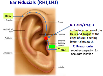
Use the helix-tragus junction for fiducials
Pre-auricular points are palpable anatomical features but are challenging to locate in anatomical MR head images and 3D EEG electrode scans. Furthermore, some experiment protocols call for using other anatomical points on the ears (e.g., ear canal, ear lobes, etc.) while retaining the inaccurate pre-auricular labels. While consistency is critical when gathering data for a study, collaborative or data mining projects are undermined when accurate labels or descriptions are not used. With photogrammetry improving the availability of electrode localization, we strongly recommend using the helix-tragus junction (LHJ & RHJ) as the ear fiducials: these points are identifiable in 3-D head models as well as MR head images. This is the coordinate system we recommend for get_chanlocs, an EEGLAB plug-in for photogrammetric electrode localization using 3-D head models.